The basis of the studio was to investigate the impact of digital technologies for the production of architecture, focused in the implementation of parametric design tools and digital fabrication equipment.
We had to study an existing house in order to find particular elements which affected it on order to apply the parametric tools to create a basic model which could respond to this elements.
Our choice was "Casa Tolo" by Portuguese architect Alvaro Leite Siza, because we wanted to create a parametric house which could adapt itself to any given topography as a basis. We know by experience that we do not live in a planar world, every site has a determined topography which affects the way we design, we know that there are several ways to attack this situation, you could ignore the topography and create a structure to solve a simple design, a response which often affects the whole environment, or you could take advantage of this topography to adapt your design to it.

Pictures of house by Images_ Fernando Guerra / FG+SG (http://www.ultimasreportagens.com/)
Images from article by Carlos J Vial
Top Solid Model
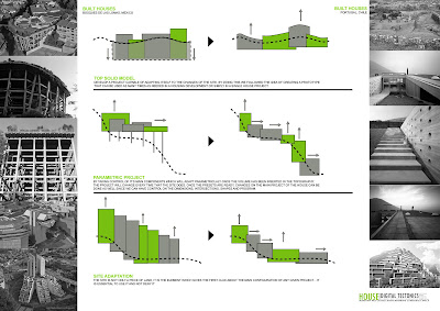
Our idea was to develop an associative model capable of adapting itself to the changes of the site, by doing this we followed the idea of creating a prototype which can be used as many times as needed either for a housing development as mass customization, or in a single house project.
By taking control of its main components which will adapt parametrically once the volume is inserted in the topography, the project changes every time the site does. Once the presets are ready, the changes on the house can be made as well, since we can control dimensions, intersections, shapes and program.
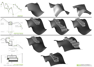
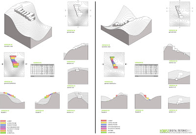
- The project had different control parameters, the first set was in a global scale, directly related to site and volumes.
- The possibility to modify the site itself, topography.
- The option to control the position of each block with a certain restraints (always connected to each other)within the site. So you could go uphill, downhill or to either side.
- The chance to control the height of each element in order for them to stay connected through the topography.
- You could change numerically the width of every element of the house, walls, slabs and ground slab.
- The opening for windows on either side of the element, working with the intersection between each box.
- The intersection between each box can also be changed numerically, by height or by the width of the staircase.
- The possibility to work with different programs of the house depending on the topography, whether downhill, uphill, or both at the same time.
- The automatic creation of the stairs needed to connect each element respecting the inclination and size of real regulations, this automatically gave the dimensions needed for each element to work with this staircase whether it goes up or down.(boxes length)
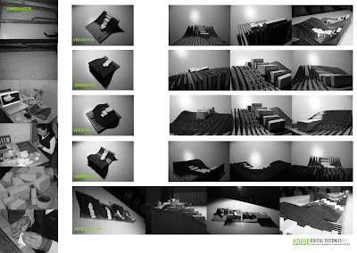
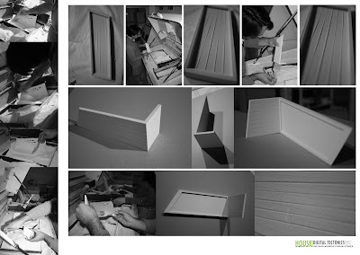
We created a series of models which represented some of the basic ways the project could work, all this models came directly from the parametric model, even the cutting plans changed when you changed the model, this was laser cut and put together showing the direct advantages of associative software linked to digital fabrication methods.
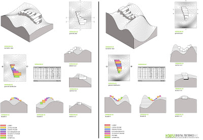
At the same time, we incorporated a program for each of this chosen configurations, and we ended up making a second set of parameters for one of this possibilites.
Here you can see a video of how the actual model works in Missler's Top Solid:
The second set of parameters worked in a different scale. The idea was to go further into the possibilites of parametric software in the detailing and actual construction of the house.
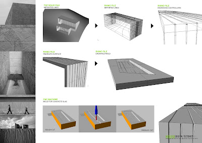
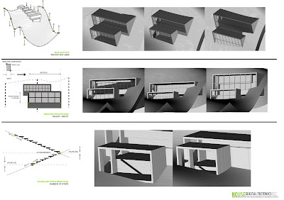
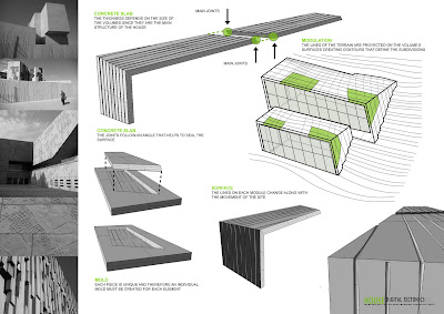
- First we projected the topography lines directly to the outer surface of each box, in order to use them as a base for marking the surface, thinking of them as precast concrete elements.
- These precast elements can be further developed in another software such as Rhino, in order to subdivide the surface and create a CAM file which could be used for molds of each element. Giving us the chance to subdivide the elements using the same carvings so you would not see the joints.
- On the other hand we were able to control the subdivisions for the profiles of the windows, the size of this profiles, and the number of elements in which to divide the facade.
We went a little further also with the staircase, and you could control the size of each step, the width of the staircase, the with of each step, depending on material needs, and even the railings height, and with according also to the material wished to apply.
Here you can see a video of how this parameters work in Missler's Top Solid:
We created some models in the 3d rapid prototyping printer to show in scal how both the mold and the actual corner piece would work. And we developed the Rhinocam files of the mold considering the use of a 3 axis CNC-Milling Machine with foam.
Masters Works
IaaC 2007-2008Research Studio in Digital Tectonics
Tutors: Marta Male-Alemany - Jose de Pedro Sousa
Authors: Rodrigo Langarica Avila -

No comments:
Post a Comment